55 Results
View results:
Sort by:

Using the Timber Design add-on, timber column design is possible according to the 2018 NDS standard ASD method. Accurately calculating timber member compressive capacity and adjustment factors is important for safety considerations and design. The following article will verify the maximum critical buckling strength calculated by the Timber Design add-on using step-by-step analytical equations as per the NDS 2018 standard including the compressive adjustment factors, adjusted compressive design value, and final design ratio.

Wind direction plays a crucial role in shaping the outcomes of Computational Fluid Dynamics (CFD) simulations and the structural design of buildings and infrastructures. It is a determining factor in assessing how wind forces interact with structures, influencing the distribution of wind pressures, and consequently, the structural responses. Understanding the impact of wind direction is essential for developing designs that can withstand varying wind forces, ensuring the safety and durability of structures. Simplified, the wind direction helps in fine-tuning CFD simulations and guiding structural design principles for optimal performance and resilience against wind-induced effects.

Compliance with building codes, such as Eurocode, is essential to ensure the safety, structural integrity, and sustainability of buildings and structures. Computational Fluid Dynamics (CFD) plays a vital role in this process by simulating fluid behavior, optimizing designs, and helping architects and engineers meet Eurocode requirements related to wind load analysis, natural ventilation, fire safety, and energy efficiency. By integrating CFD into the design process, professionals can create safer, more efficient, and compliant buildings that meet the highest standards of construction and design in Europe.

The events of recent years remind us of the importance of earthquake engineering in seismic regions. For you as an engineer, the design of structures in earthquake-prone areas is a constant trade-off between economic efficiency – the financial possibilities – and structural safety. If a collapse is inevitable, engineers must estimate how it will affect the structure. This article aims to provide you with an option on how to perform this estimation.

When modeling and designing glass panes in RF-GLASS, you have two different options for the FE mesh settings.

Designing vertical insulating glass requires assigning different loads on the individual layers of the entire glass unit. This occurs, for example, with simultaneous actions from wind loads and fall protection.

To work even more efficiently, RF‑GLASS allows you to create and save different, user‑defined layer structures that can be reimported later or loaded in another project.

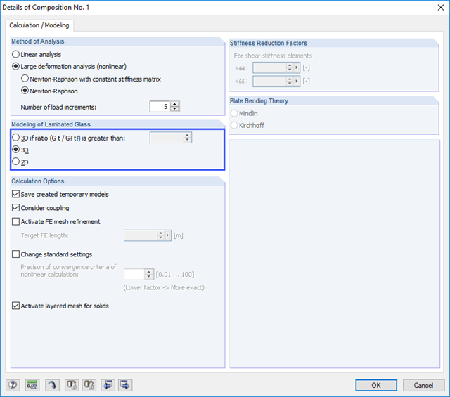
For designing glass in the RF‑GLASS add‑on module, you can use one of two calculation methods: a 2D or a 3D calculation. The main difference between these design options is the automatic modeling of the layers in a temporary model. In a 2D calculation, each layer is generated as a surface element (plate theory); in a 3D calculation, it is generated as a solid. Depending on the selected layer composition, you can either select an option or find it preselected by the program.

In the RF-GLASS add-on module, 3D rendering is implemented to facilitate the definition of the support conditions. This interactive graphical visualization facilitates the input and control of line and nodal supports. However, the schematic display can also be selected, if necessary.

In the case of wall-like load-bearing behavior of the cross-laminated timber plate, special attention must be paid to the shear deformation in the plane of the pane and thus, in particular, to the displaceability of the fasteners.

In the "Edit Load Cases and Combinations" dialog box, you can combine different load cases in one load combination under the "Load Combinations" tab.

The support of the cross-laminated timber panel deserves special attention. Usually, a cross‑laminated wall is secured against shearing by means of shear connectors and against lifting forces by means of tie rods.
One of the advantages of entering the structure in RFEM is the complete freedom when selecting the geometry. You can easily select a structure where re‑entrant rolling corners are given as shown in the image.
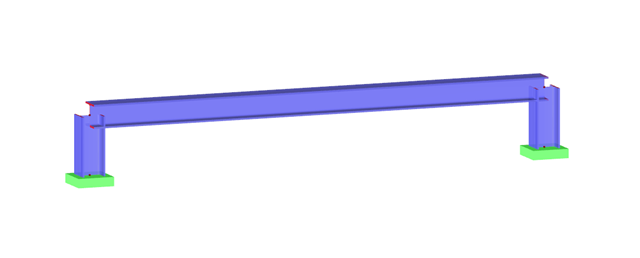
This time, we will look at modeling downstand beams using ribs.

When using the RF‑GLASS add‑on module, you can define just the geometry in the main program, as well as the load situation of the structural component to be designed. The respective support conditions and all further design-relevant definitions (for example, the layer structure and support conditions), can be further specified in RF‑GLASS.
.png?mw=640&hash=8fd04a597cecae2e434980ce79fc626815a5d98a)
The Aluminum Design Manual (ADM) 2020 was released in February 2020. The ADM 2020 gives guidance for both the allowable strength design (ASD) and load and resistance factor design (LRFD) for aluminum members to ensure reliability and safety for all aluminum structures. This latest standard was integrated in the RFEM/RSTAB add-on module RF-/ALUMINUM ADM. The text below will highlight the applicable updates relevant to the Dlubal programs.

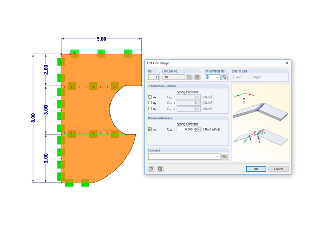
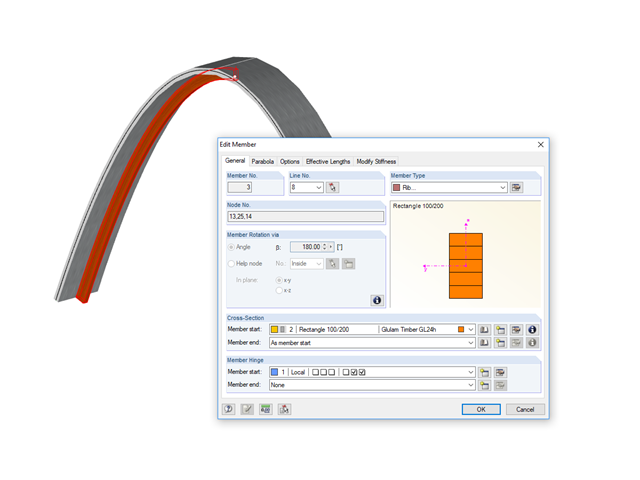
For cross‑laminated structures with large spans, downstand beams or hybrid structures are often used. They can be modeled in RFEM 5 by using surfaces and member cross‑sections. In both structural systems, curved downstand beams are also possible without any problems. In the case of the curved surface, the member is always appropriately generated by means of the automatic member eccentricity with the thickness distance of the surface and the member. The downstand beam can also be connected flexibly by means of a line release.
In this article, we will look at the design of shear connectors of cross‑laminated timber structures that transfer the longitudinal forces of the shear wall to the soil.
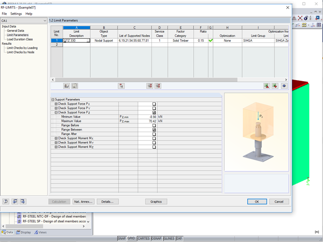
Usually, the lifting forces acting on a structure, which mostly result from wind loads or a dynamic analysis, are transferred into the ground through ties.

In addition to the basic combination rules of EN 1990, there are other combination conditions for actions on road bridges specified in EN 1991‑2 that must be taken into account. RFEM and RSTAB provide automatic combinatorics that can be activated in the General Data when selecting the standard EN 1990 + EN 1991‑2. The partial safety factors and combination coefficients depending on the action category are preset when selecting the respective National Annex.
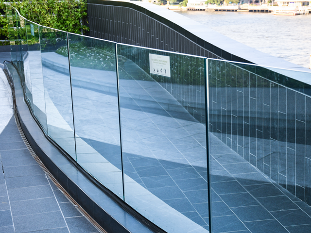
The architectural requirements for guardrails are still very high, and railings usually require a high degree of transparency. Glass railings, which do not require a visible support frame, offer a possible solution.

Using the RF-TIMBER CSA module, timber column design is possible according to the CSA O86-19 standard. Accurately calculating timber member compressive resistance and adjustment factors is important for safety considerations and design. The following article will verify the factored compressive resistance in the RFEM add-on module RF-TIMBER CSA, using step-by-step analytical equations as per the CSA O86-19 standard including the column modification factors, factored compressive resistance, and final design ratio.

Using the RF-TIMBER AWC module, timber column design is possible according to the 2018 NDS standard ASD method. Accurately calculating timber member compressive capacity and adjustment factors is important for safety considerations and design. The following article will verify the maximum critical buckling in RF-TIMBER AWC using step-by-step analytical equations as per the NDS 2018 standard including the compressive adjustment factors, adjusted compressive design value, and final design ratio.
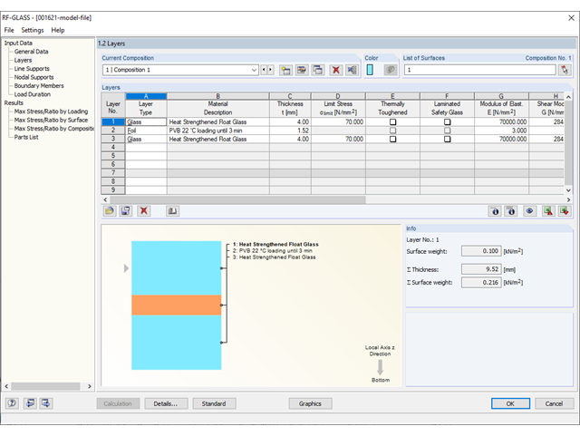
Different glass types and layer structures are available for glass structures used for different purposes. The following types are usually used: float glass, partly tempered glass, and toughened safety glass.
Due to the special properties of glass, you also have to pay close attention to the details when modeling in an FE model. Glass has a very high compressive strength and is, therefore, generally only designed for its tensile stresses. One particular disadvantage of the material is its brittleness. Stress peaks that occur in the calculation must, therefore, not be readily neglected.
Modeling planar structural components such as glass panes is generally possible only in RFEM. If it is necessary to define the stiffening effect of a pane in a particular case, it can also be simulated in RSTAB.

Using the RF-TIMBER CSA module, timber beam design is possible according to the CSA O86-14 standard. Accurately calculating timber member bending resistance and adjustment factors is important for safety considerations and design. The following article will verify the factored bending moment resistance in the RFEM add-on module RF-TIMBER CSA using step-by-step analytical equations as per the CSA O86-14 standard including the bending modification factors, factored bending moment resistance, and final design ratio.
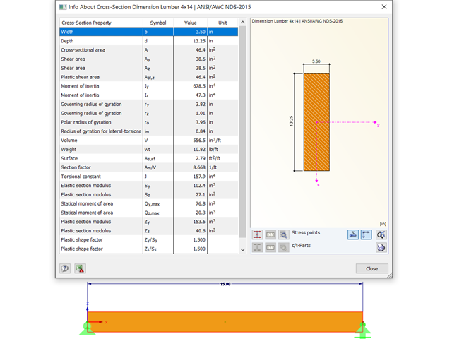
Using the RF-TIMBER AWC module, timber beam design is possible according to the 2018 NDS standard ASD method. Accurately calculating timber member bending capacity and adjustment factors is important for safety considerations and design. The following article will verify the maximum critical buckling in RF-TIMBER AWC using step-by-step analytical equations as per the NDS 2018 standard, including the bending adjustment factors, adjusted bending design value, and final design ratio.

Using RF-CONCRETE Members, concrete column design is possible according to ACI 318-14. Accurately designing concrete column shear and longitudinal reinforcement is important for safety considerations. The following article will confirm the reinforcement design in RF-CONCRETE Members using step-by-step analytical equations as per the ACI 318-14 standard, including required longitudinal steel reinforcement, gross cross-sectional area, and tie size/spacing.
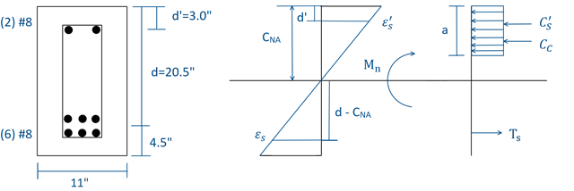
Using RF-CONCRETE Members, concrete beam design is possible according to ACI 318-14. Accurately designing concrete beam tension, compression, and shear reinforcement is important for safety considerations. The following article will confirm the reinforcement design in RF-CONCRETE Members using step-by-step analytical equations as per the ACI 318-14 standard, including moment strength, shear strength, and required reinforcement. The doubly reinforced concrete beam example analyzed includes shear reinforcement and will be designed under the ultimate limit state (ULS) design.